|
Abstract: Accurate measurement of the
third order intercept point for low distortion components such as the MGA-72543 requires
some precautions to be observed in the test setup and selection of test equipment. This
discussion focuses on making successful measurement of third order intermodulation
products and calculation of the input and output intercept points.
Introduction
Accurate measurement of intermodulation distortion for the
MGA-72543 requires some precautions to be observed in the test setup. This discussion will
focus on third order intermodulation products and calculation of the input and output
intercept points.
The basic setup for measuring intermodulation distortion is shown in Figure 1.
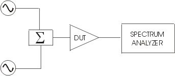
Figure 1. Basic IM Test Setup.
In the basic IM setup, two fundamental signals are combined and applied
to the input of the device under test (DUT). Third order distortion products generated by
the DUT are then measured by the spectrum analyzer.
There are three sources of error that should be considered when making distortion
measurement on devices with relatively low intermodulation products. These are:
- Interaction between the test equipment
- Dynamic range of the spectrum analyzer
- Quality of the test equipment
Test equipment interaction
The preferred method for combining the two
signal generator outputs is to use a resistive power combiner. A resistive combiner has
the advantages of being well-matched at all three ports and presents a constant,
power-independent impedance to both of the signal sources as well as the device under
test. In addition, a resistive combiner is frequency insensitive (broadband) and being
virtually completely linear, creates no intermodulation products of its own.
One of the most important considerations in making IM measurements is to provide
adequate isolation between the two signal generators. If the two signal generators are not
well isolated from one another, their ALC circuits can interact in such a way as to
produce excessive IM products. The best choice for isolating the signal generators is to
place a ferromagnetic isolator between each signal generator and the power combiner.
A less desirable alternative is to substitute fixed attenuators, e.g., 10 to 20 dB, for
the isolators. Although attenuators have the advantage of making the test setup broadband,
the isolation is not as high and increasing the output power level from the signal
generator to compensate for the attenuation may introduce additional distortion into the
signals.
Placing a fixed attenuator (e. g., 6-10 dB) between the power combiner and the input
port of the device under test is an extra measure that will ensure the test device is
presented with a constant impedance source. Similarly, an attenuator between the test
device's output will ensure a good match for both the spectrum analyzer and DUT.
A test setup implementing these accuracy enhancements is shown in Figure 2.
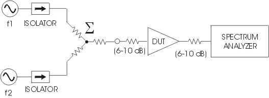
Figure 2. Enhanced Accuracy Setup.
Dynamic range of the test equipment
One of the challenges of measuring high intercept point devices
is that of dynamic range. A wide dynamic range is necessary to simultaneously measure very
low level IM products while in the presence of large fundamental signals. The dynamic
range of the spectrum analyzer is limited on the low end by its sensitivity, or noise
floor. The upper end of the analyzer's dynamic range is limited by the maximum input
signal level for which the distortion products generated within the analyzer itself are
below a level that would obscure the measurement.
Excessively high input signals to the spectrum analyzer may create internal distortion
products that could be mistaken for the actual distortion to be measured on the device
under test. To maximize the dynamic range of the spectrum analyzer, the input signal level
to the analyzer should be kept as low as possible consistent with still being able to
observe the third order IM products.
The usual quick check to determine if the analyzer in generating internal distortion
due to input signals that are too high, is to increase the analyzer's input RF attenuator
by 10 dB and verify that there is no change in the signal level of the IM products. If the
IM product levels do change when the input attenuator is switched, the analyzer is
generating internal distortion products and the input signal level is too high to make a
valid measurement.
Quality and accuracy of the test equipment
Other factors affecting intermodulation measurement accuracy
are related to the quality of the test equipment. Synthesized signal generators are the
recommended choice for the two fundamental signal sources. For even greater measurement
sensitivity, it may be desirable to select signal generators with low noise options.
Much of the accuracy of the measurement is related to the quality of the spectrum
analyzer. Of key importance, analyzers should be chosen with adequate dynamic range
specifications. Low noise options may also be useful in improving the sensitivity for
observing low-level IM products.
Calculating the intercept point
After ensuring that an accurate measurement of the
intermodulation products has been made, the third order intercept point is calculated as
follows:
OIP3 = Po + DIM/2
where OIP3 is the third order intercept point (in dBm) referred to the output of the
device under test, Po is the output power level of either of the two fundamental signals
(in dBm), and IM is the difference in signal level (in dB) between the fundamental and the
third order intermodulation products. The signal levels as observed on the spectrum
analyzer are depicted in Figure 3.
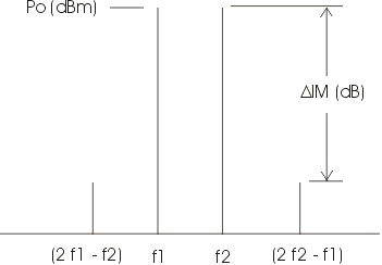
Figure 3. Fundamental and IM Signals.
The input third order intercept point is then:
IIP3 = OIP3 - Gain
where IIP3 is the third order intercept point (in dBm) referred to the input of the
device under test and Gain is the test device gain in dB.
Summary
Key factors for the successful measurement of IP3 for low
distortion components such as the MGA-72543 are: use of synthesized signal generators,
effective isolation between the signal sources, and ensuring the spectrum analyzer is not
contributing IM products that obscure the test results. Other test setup enhancements may
also be necessary depending on the particular test equipment used.
|